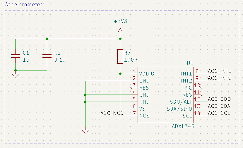
ADXL345 Development Board

View Github Repo

Tools Used

Software/Languages:

Schematic

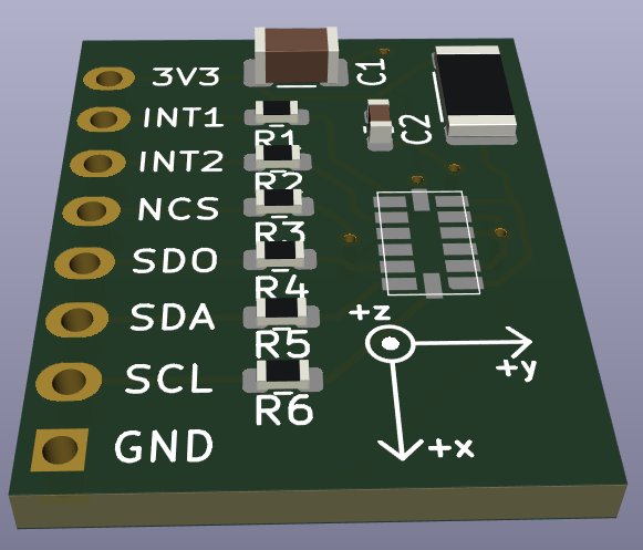
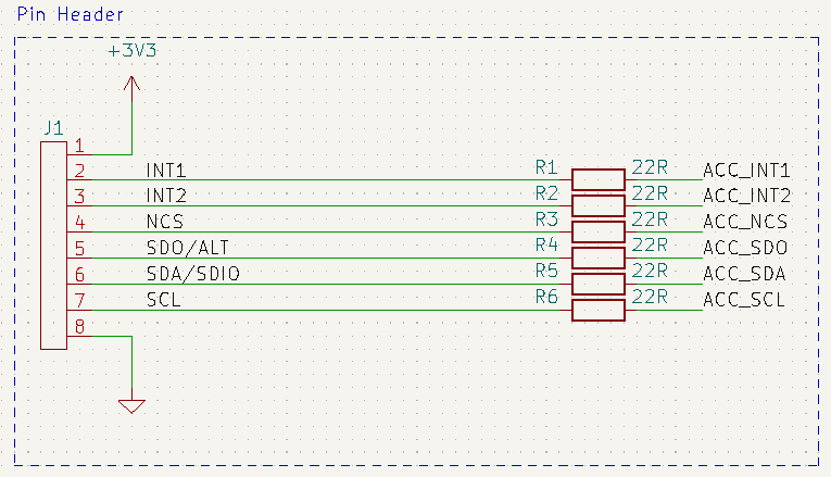
The schematic is divided into 2 parts: the pin header and the accelerometer IC. There are communication series resistors on the input/output lines. The accelerometer Has power supply decoupling capacitors as well as a decoupling series resistor as advised in the datasheet.

Pin Header:

Accelerometer:

Custom Footprint

A custom footprint was required for the ADXL345. This was done by following the measurements given in the recommended printed wiring board section of the datasheet (p.35).

ADXL345:

PCB:

The design goals were to create a functional, testable and small development board. It is intended to be soldered with male pin headers and offers a silkscreen drawing for reference to the direction of axes.

PCB Editor view:

3D viewer:

Sources and Datasheets